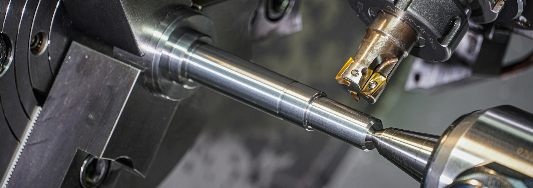
What is a machining tolerance?
A tolerance defines the permissible variation in a dimension. A shaft specified as ⌀25.00 ±0.05 mm may be anywhere between 24.95 and 25.05 mm and still be acceptable. The tolerance band - 0.1 mm in this case - determines how precisely the machine must hold the dimension, which directly determines how long it takes and how much it costs.
Tolerances are typically expressed as bilateral (±0.05), unilateral (+0.00/-0.10), or using ISO tolerance grades (h6, H7, etc.). For mating parts, the relationship between shaft and bore tolerances determines whether you get a clearance, transition or interference fit.
Standard tolerances in CNC machining
For CNC milling and turning, the following ranges reflect what is achievable without special process controls:
| Grade | Typical tolerance | Surface finish Ra | Typical application |
|---|---|---|---|
| General machining | ±0.1 mm |
3.2 µm |
Non-critical features, clearance holes, external profiles |
| Standard precision | ±0.05 mm |
1.6 µm |
Bearing seats, locating features, general fits |
| High precision | ±0.01 mm |
0.8 µm |
Close-fit bores, precision shafts, hydraulic components |
| Ultra-precision | ±0.005 mm |
0.4 µm |
Gauge surfaces, precision instruments, aerospace features |
Most production parts are designed to ±0.05-0.1 mm on non-critical features. Tighter tolerances on every dimension add cost without adding function.
How tolerances affect machining cost
Tighter tolerances cost more for three reasons:
- Slower feeds and depths of cut. Holding
±0.01 mmrequires finish passes at reduced speed, which increases cycle time. - More measurement steps. Each tight-tolerance feature must be measured - often multiple times during the process. CMM time and skilled operator time are expensive.
- Higher reject risk. The closer a dimension is held, the more likely a marginal part ends up as scrap. Manufacturers price this risk into tighter-tolerance work.
A part with five tight tolerances where only two are functionally necessary can cost 30-50% more than it should. Spend time identifying which tolerances are truly critical before finalising a drawing.
As a rule: specify the loosest tolerance that still ensures correct function. Reserve ±0.01 mm and tighter for features that genuinely require it - bore diameters for hydraulic seals, bearing seats, precision fits.
ISO tolerance grades and fits
The ISO system defines tolerance grades from IT1 (finest) to IT18 (coarsest). For general machined parts, the practical range is IT6 to IT11:
| Grade | Tolerance on ⌀25 mm | Typical use |
|---|---|---|
| IT6 | 13 µm |
Precision shafts, close fits |
| IT7 | 21 µm |
Standard bearing seats, H7/h6 fits |
| IT8 | 33 µm |
General precision machining |
| IT9 | 52 µm |
Non-precision fits, clearance features |
| IT11 | 130 µm |
Rough machining, non-functional dimensions |
Standard H7/h6 (clearance fit) and H7/p6 (interference fit) cover the majority of engineering applications. Unless your drawing specifies otherwise, most CNC suppliers will work to IT8-IT9 on untoleranced dimensions.
Surface finish and its relationship to tolerance
Surface finish (Ra) and dimensional tolerance are related but independent. You can have a tight tolerance with a relatively rough surface - for example, a precision-ground bore that still shows tool marks. In practice, achieving Ra 0.4 µm typically requires grinding or honing in addition to turning or boring, which adds operations and cost.
Standard CNC turning achieves Ra 1.6-3.2 µm. Finishing passes bring this to Ra 0.8 µm. Grinding, honing or lapping are required for Ra 0.4 µm and below.
Practical recommendations
- Tolerance only what matters. Add tight tolerances only to features that determine fit, function or assembly.
- Use standard fits. H7/h6, H8/f7 and similar standard fits cover most engineering needs without custom tolerance analysis.
- Specify surface finish separately. Do not assume tight tolerance implies fine finish - call out Ra explicitly where it matters.
- Talk to your manufacturer early. Suppliers can often suggest small design changes that make a part significantly easier to hold to tolerance.
- Check your drawing defaults. Most title blocks define a default tolerance for unspecified dimensions - make sure yours reflects what you actually need.